Statistical Process Control (SPC), specifically control charting, is commonly used throughout the industrial world to monitor a plethora of processes in an efficient and timely fashion. The real attraction is the ability to monitor variables that directly impact the quality of a product live, and therefore correct anything on the go, saving time and money. With the advancement of CATI center technologies and CAPI surveying devices, there is an opportunity to take advantage of real time data to improve quality through control charting in survey research. This article highlights some of the basic ideas behind control charting through an example that monitors interview length as a key quality characteristic because of its direct relationship with response rates and cost.
Much of quality control within survey research is conducted in similar fashion to acceptance sampling, which is one of the earliest forms of quality control within the industrial realm. It consists of taking a sample from a lot, with some quality characteristic inspected, and on the basis of the investigation accepting or rejecting the lot. Acceptance sampling has become de-emphasized within industry because it is “too late, costly and ineffective.”[1]
This is not to discredit the usefulness of non-live quality control. D3 Systems, Inc. maintains a consistent quality control assessment of its interviewers by performing various checks on interviewer performance via the final data. Most of these tests are comparing the performance of an interviewer to his or her peers. For example, average interview length, percent of straights across a question battery, non-response percentages, etc. This form of quality control still has its merits, especially when interviewers are used over multiple projects. Since these interviewers are assigned unique IDs, their performance on a certain project is assessed and their inclusion in a future survey depends on their performance. Nonetheless, it is still after-the-fact analysis. Corrective action is only done after the survey is finished.
However, this form of post-hoc quality control is the only practical approach in many, if not the majority, of environments in which D3 works. Due to the company’s focus on post-conflict environments and hard to reach areas throughout the world, face-to-face interviews are often the best, not to mention the only viable source of interviewing. The travel of interviewer information from field, to data collection center, to key puncher, to management runs on a timeline that is simply impractical for live quality monitoring.
On the other hand, the application of control charting to live interviewer performance data, when possible, allows management to statistically monitor the performance of their interviewers and projects in a proactive fashion. Instead of performing quality control periodically during a survey or after the fieldwork is completed, live data analyzed consistently through these charts allows one to investigate and take corrective actions while the process is ongoing, ultimately resulting in a consistently higher quality end product.
Old vs. New Philosophy
Our quality characteristic, or characteristics, of choice usually have an ideal target value. In survey research, these can be any of the many variables measured in a standard disposition report. This variable can then be monitored for example in terms of its mean by way of control limits, which can then aid in determining whether or not the variable we are monitoring is on the right track.
For example, D3 Systems, Inc. conducts various monthly National Surveys in the Middle East. Following fieldwork, quality control testing is performed on the interviews that have been completed. One of the tests that the face-to-face QC report focuses on is interview length. In a previous survey the mean interview length was 21.67 minutes.
D3 has established limits of ±1 standard deviation for this particular test. In this case, the tolerance limits resulted in 15.24 and 28.1. If an interviewer’s average length fell between these limits they were not flagged.
Although this method does take into account the field’s average, it still adheres to the old philosophy of being within tolerance limits as good enough.
With SPC Control Charting coupled with live CATI technology, the process can be forced to be on target and a focus can be placed on constant reduction in variability, all directly related to the overall quality of the final product because monitoring is being done live, and not after the fact.
In other words, the prior philosophy has no motivation to improve if it is within the limits while the latter promotes constant improvement.
Consider the following simulation based on real interview length data.[2] Choosing a good variable to monitor is important and details need to be considered when choosing one. Rationale for choosing interview length include: its relation to interviewer/respondent rapport, survey cost, and the fact that it is a continuous variable.
Phase I
The first step is to take base-line samples of the process in question over time. In this particular case, live disposition data was recorded at an hourly rate for a D3 Systems, Inc. monthly National Survey in the Middle East.
The goal of Phase I is to collect data and determine what is “in control” for the process under study. One can almost view it as a pilot study, trial data that helps determine how to proceed during future sampling and monitoring. Trial control limits are established based on this data.
Traditionally, in industrial processes, it is recommended that at least 20 samples be taken during Phase I (Montgomery 2009) to accurately calibrate the control limits. However, it is common in our line of work to see an initial adjustment period for interviewers at the beginning of a project to the questionnaire design. For example, complicated skip patterns or slightly different forms of Arabic used by certain segments of the target population may result in initial interviews having a longer duration than the remainder of the project. Depending on the experience and know-how of the manager, it may be more accurate if the samples selected for Phase I are taken after this adjustment period.
If a pilot study doesn’t provide enough time to collect such a sample, using a previous wave of the same survey may be helpful as well. In other words, if we have historical data, it may be of benefit to include it in our Phase I analysis. This is what was done for this particular project. Note that the variables, such as interviewers, calling center, target population, etc. all remained constant from the last survey to the present. If any of these sources of variability change, it is recommended that base pilot data be taken from the actual current survey.
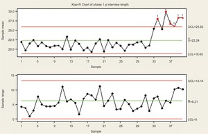
The following control chart focuses on the quality characteristic variable of interview length. As noted before, a baseline sample from the previous wave was taken to prepare Phase I control limits. For this particular case, 40 samples were taken at an hourly rate, each consisting of 5 observations (interviews).
The primary steps of Phase I consist of plotting the sample taken. In this case, we used a Shewhart Xbar-R chart. The first chart monitors the mean interview length, while the second chart monitors the samples moving range.[3] One should first focus on the range chart, then shift focus to the Xbar chart.
Any points outside of the UCL (upper control limit) and/or LCL (lower control limit) should be investigated because at those specific times, due to either the range (R chart) or the mean (X-bar chart) shifting significantly.
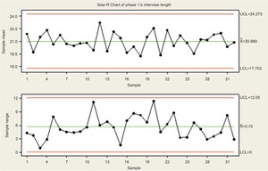
Assume a hypothetical situation for Figure 1, which signals the process out of control at the 34th sample in the Xbar chart. After further investigation, it was noted that the increased interview length was due to the introduction of new interviewers as a result of a client request. Therefore, new interviewer training took place around this time and all interviews were significantly longer. As a result, these observations were removed from the baseline data for Phase I and control limits were recalculated in Figure 2. This is the iterative process of identifying assignable causes and removing them from Phase I calculations to determine suitable control limits.
Control limits tightened as a result of the removal of these assignable causes, and it was determined that the control limits of 24.757 and 17.703 were in fact desirable for monitoring the average survey length (Xbar chart) in the current survey.
What exactly are desirable control limits, one may ask? This contains a subjective element during Phase I. For example, certain processes may appear to be in control. While the previous data was simulated, our partners have been surveying in the target country for some time and have established a consistent product over the years. As a result, when looking at control charts for various quality characteristics of interest, the process may appear to be in control, and there may be a lack of identifiable assignable causes.
However, even if a process appears to already be in control during our Phase I analysis, there is the opportunity for constant improvement by tightening the control limits. If the process is already functioning within the goal-posts, we can strive for an even better and consistent product by manually tightening the “guard-rails,”
Phase II
Once Phase I is completed and adequate control limits are determined, Phase II focuses on monitoring the process at hand.
With the assumption that the process is reasonably stable, Phase II allows one to focus on bringing any sudden shifts in process performance to light. The previously discussed chart is ideal for Phase I because they detect large, sustained shifts in a process. However, in Phase II, because we are performing live monitoring on a project in field, we are more interested in detecting sudden and quick shifts to perform corrective action as fast as possible. Although there are additions[4] that can be implemented to increase the sensitivity of detecting shifts, the Xbar-R charts are usually no longer suitable for this goal.
Cumulative sum (CUSUM)[5] and exponentially weighted moving average (EWMA)[6] control charts are usually prime candidates for Phase II control charting. Their intricate details are left out of this discussion, but a key point is that they, unlike Xbar-R charts, do not only use the information about the process contained in the last sample observation. Therefore, they are better able to detect quick shifts in the process.
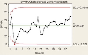
An EWMA chart was chosen to monitor our Phase II example. This particular graph monitored the first 200 interview lengths. One can note that the chart signaled the process was out of control at the 4th sample.
After further investigation, it was revealed that interviews conducted that afternoon were largely during prayer hours; as a result, these interviews ended abruptly. Corrective action was taken and future interviews were not conducted at this time.
One can see that live monitoring provides the ability to take immediate corrective action. After the 4th sample was taken, investigation into the source of the problem was taken at a practical level and the source of the variation was found. In this case the source was the time of the day at which interviews were performed. Once this was corrected, the rest of the interviews were within the control limits and returned towards the center line. These corrective actions were taken in the field, therefore not only improving overall quality of the project, but also potentially saving money needed for additional replacement surveys to meet client contractual obligations.
W. Edward Deming
Simulations were done based on collected data with manual changes done to better illustrate the control charting examples below.
Additional detailed information regarding the Shewhart Xbar-R chart can be found online at via the NIST/Sematech Engineering Statistics Handbook from the National Institute of Standards and Technology. http://www.itl.nist.gov/div898/handbook/pmc/section3/pmc321.htm.
See http://en.wikipedia.org/wiki/Western_Electric_rules for additional details.
See http://www.itl.nist.gov/div898/handbook/pmc/section3/pmc323.htm for additional details.
See http://www.itl.nist.gov/div898/handbook/pmc/section3/pmc324.htm for additional details.


